Products
Navigator Flight Controller
SKU: BR-100367
£219.99
inc. VAT
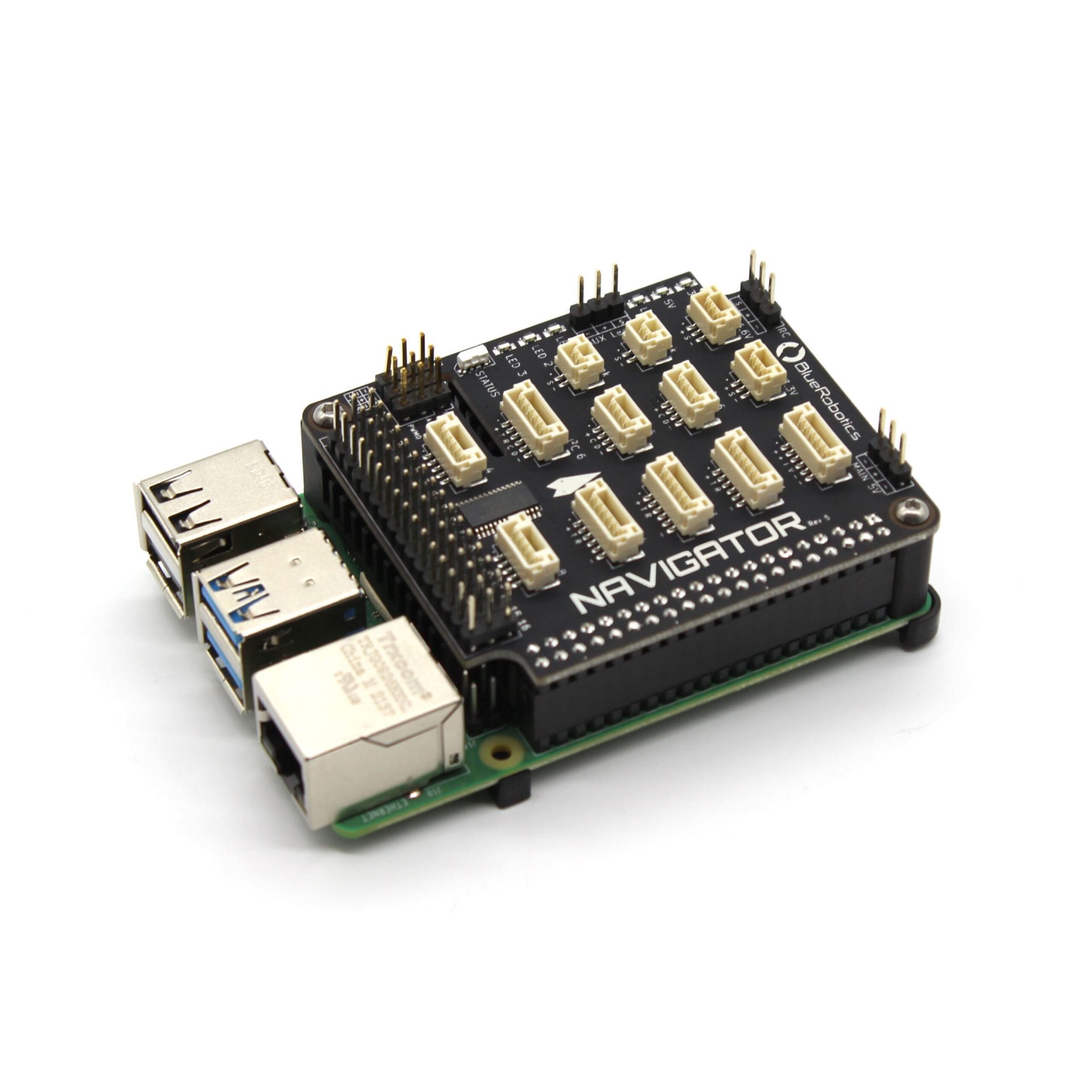
The Navigator is an ROV and robotics flight controller for the Raspberry Pi 4. It has an onboard IMU, compass, barometer, and ADC sensors as well as 16 PWM outputs and numerous serial and I2C expansion ports. The Navigator is used on the BlueROV2 and BlueBoat in conjunction with the BlueOS software, but can also be used for a wide range of robotics applications!
Raspberry Pi 4 2Gb
5V 6A Power Supply
Power Sense Module
Low Light USB camera
Configuration Total:
£219.99
Product Description
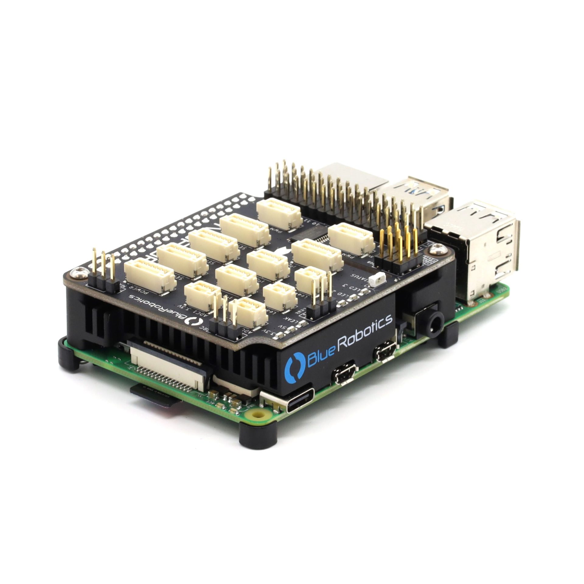
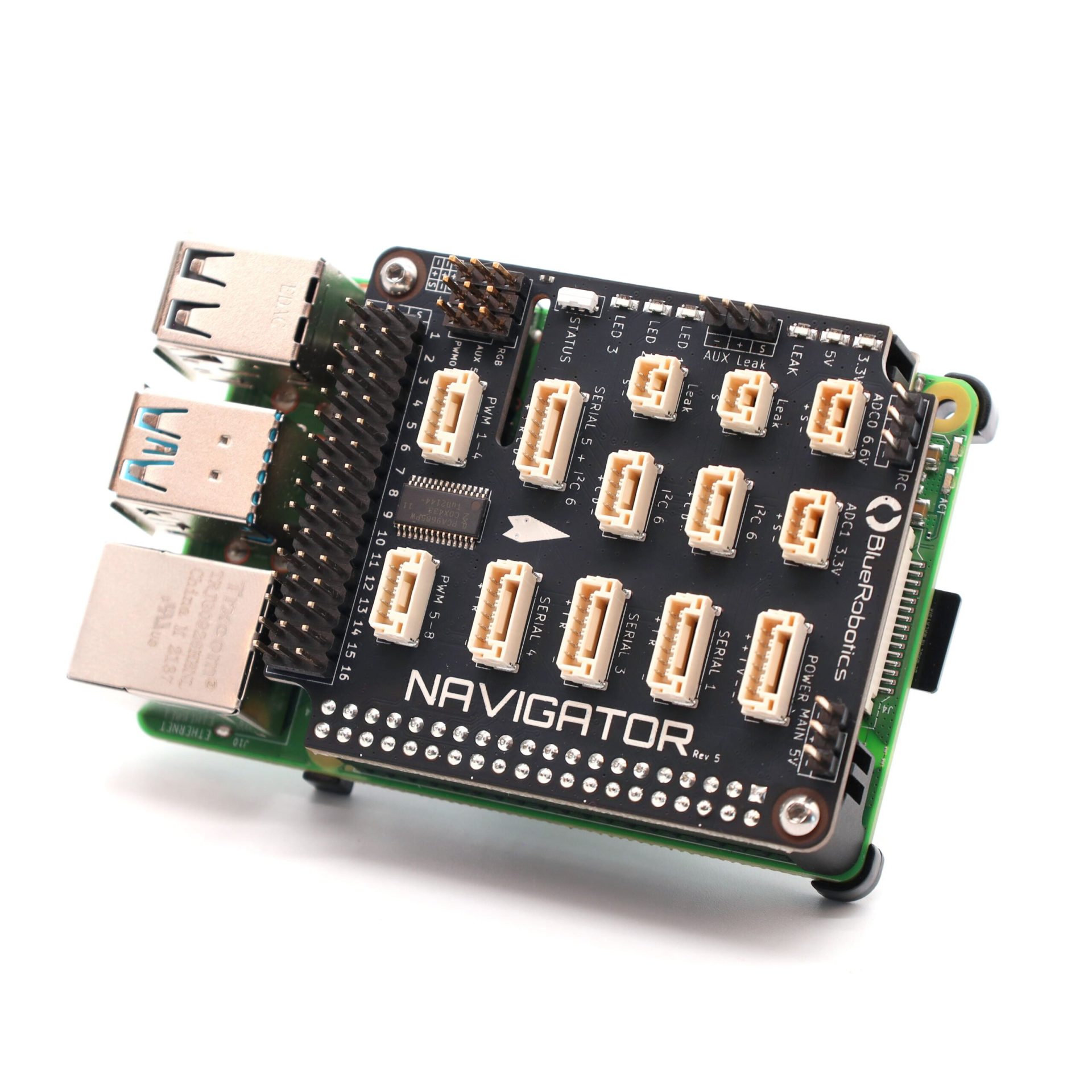
The Navigator is an expansion board that plugs into the Raspberry Pi 4 and turns it into a fully-featured flight controller, ready to power ROVs, USVs, drones, ground vehicles, and just about anything that moves!
At its core, the Navigator is a collection of inputs and outputs. It has inputs from onboard sensors, outputs to servos or speed controllers, and expansions ports that can be connected to external devices.
Onboard, the Navigator has:
- 6-axis IMU with accelerometers and gyroscopes for orientation
- Dual three-axis magnetometers for compass heading
- Barometer for altitude in air
- 16 servo PWM channel outputs
- Current and voltage ADC inputs
- Built-in leak detection for 2 probes
- RC receiver input (SBUS)
- RGB status LED
Additionally, the Navigator has expansion connectors available, all of which follow the Blue Robotics Connector Standard and are compatible with most industry autopilot accessories. It has the following expansion ports:
- 4 serial ports
- 2 I2C ports
- 2 16-bit analog-to-digital converter (ADC) ports
- External LED port compatible with Neopixel RGB LEDs
In addition, the Navigator has a number of important features that are worth highlighting:
- Dual power inputs with automatic power switching for redundancy
- 3.3V logic on all ports
- 5V tolerance on serial ports
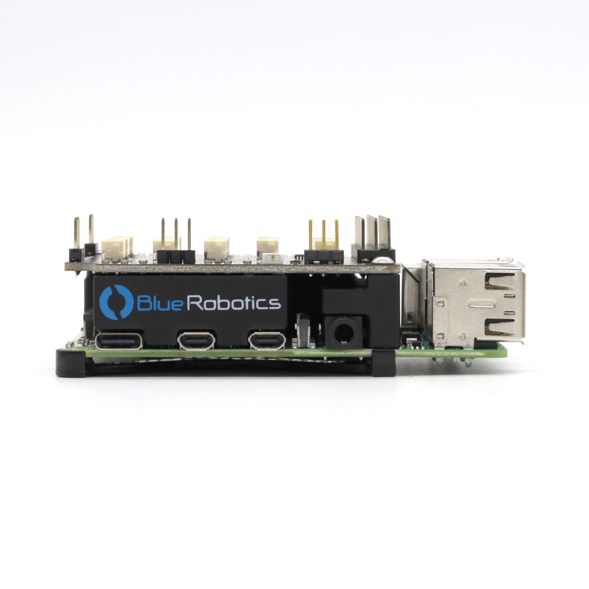
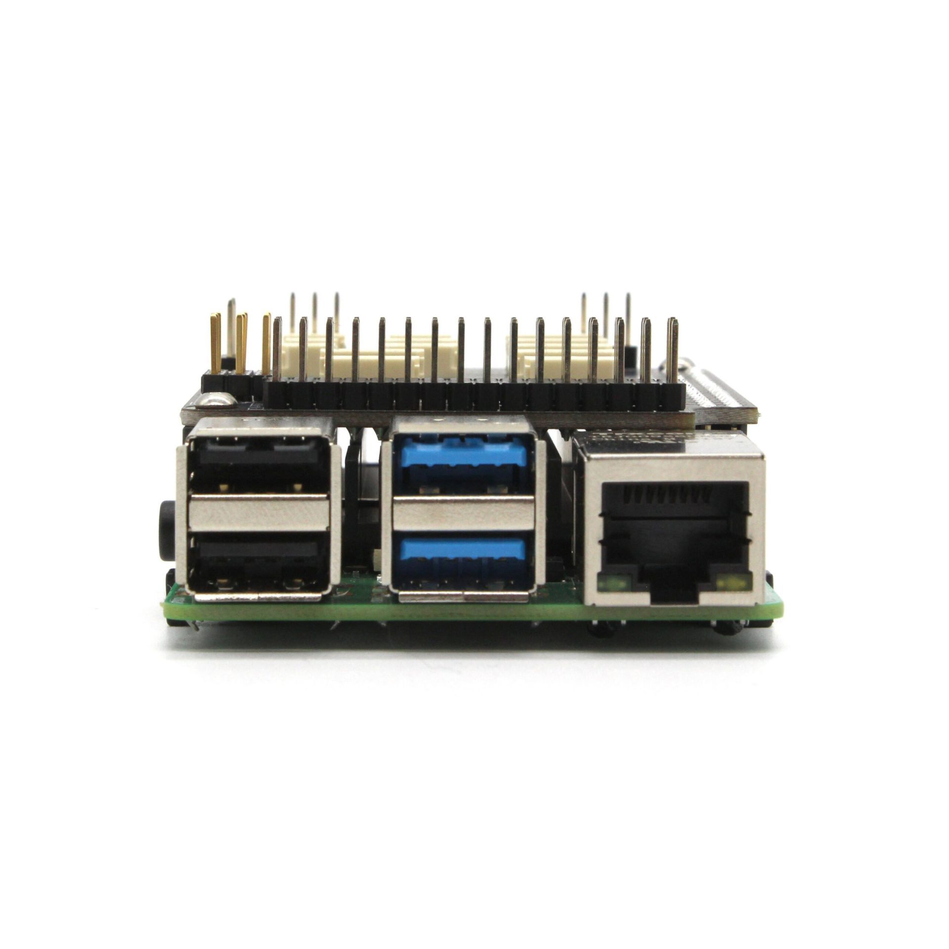
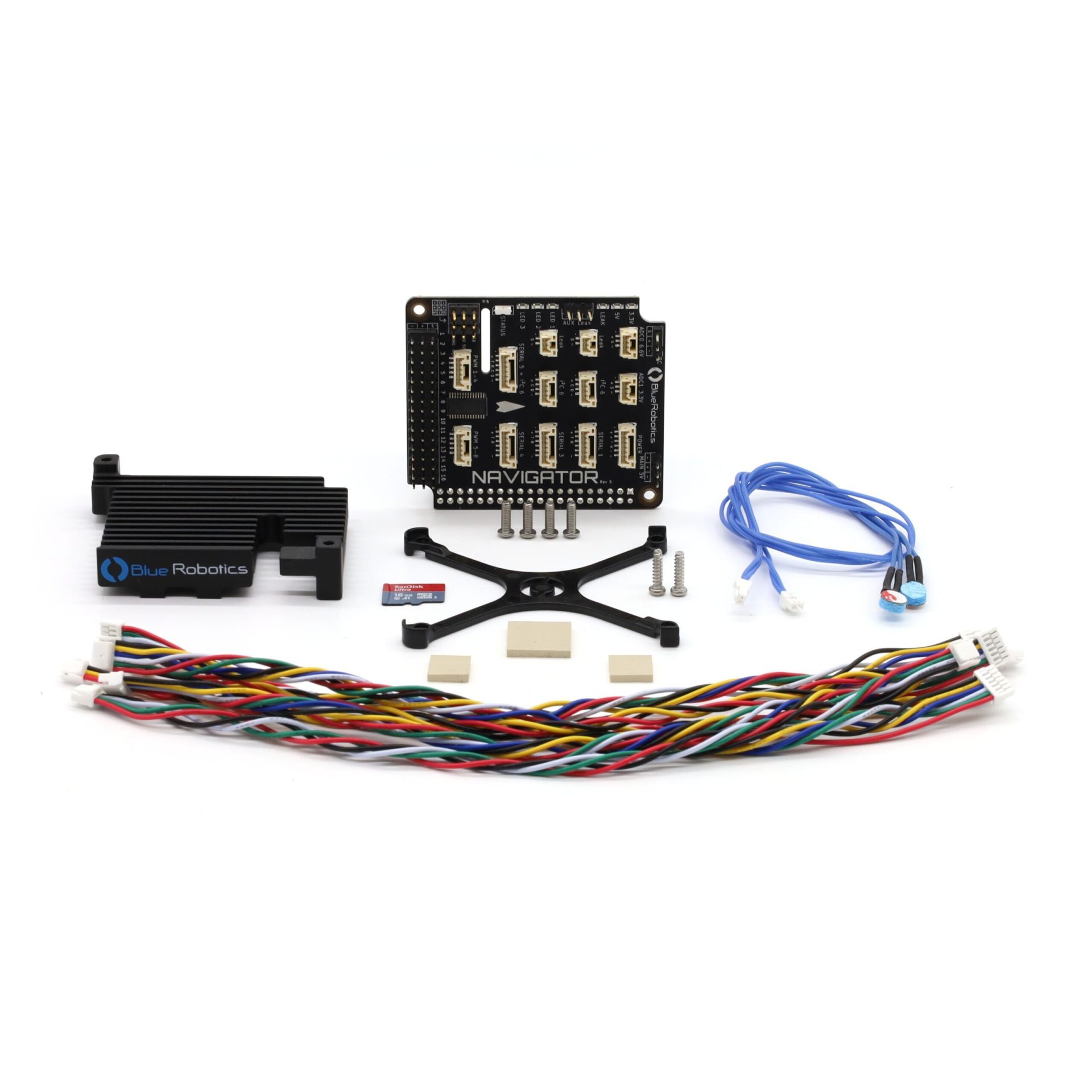
The Navigator comes with a custom designed aluminium heatsink that fits between the Navigator and Raspberry Pi and allows the Raspberry Pi to operate at high CPU usage in poorly cooled environments, like inside an enclosure. There’s a slot in the Navigator board that allows you to use the Raspberry Pi’s CSI camera connector.
The Navigator kit also comes with a set of expansion cables for the serial, I2C, and ADC ports to allow you to connect your hardware quickly and easily.
The Navigator kit ships with an SD card loaded with BlueOS, our new core operating software for ROVs, USVs, and other robotics. Built on top of Raspbian Linux, it provides a host of features including autopilot software management, video streaming, software updates, and user-defined extensions. It allows you to get started quickly with the Navigator and ArduPilot firmwares.
The Navigator schematic design is open source and available to help you maximize your usage of the Navigator.
Technical Specifications
FAQs
Didn't find your answer?
Don't hesitate to contact us.
You May Also Need

Related Products

Can't see what you need or have a query? Please just get in touch…